Estimating and measuring Moment of Inertia (MoI)
The robot's rotational inertia has a significant impact on how quickly it can follow complex, twisty paths. For the best results, it is recommended to get as accurate an estimate of this parameter as possible.
In this section, we outline various approaches to determine a resonably accurate estimate of this key property.
This article is not intended to be an exhaustive list of ways to estimate MoI. In addition, some of these techniques may be less feasible for your team, depending on your team's unique resources and strengths.
System Identification methods
If thorough System Identification has been performed, the system's MoI can be calculated from:
where \(kA_\text{angular}\) is the angular acceleration feedforward constant of the drivetrain and \(kA_\text{linear}\) is the linear acceleration feedforward constant.
Assuming a simplified mass distribution
If the robot is considered a solid rectangular plate of uniformly-distributed mass, its MoI would be:
However, this would likely be an underestimate because most FRC robots tend to have mass concentrations (e.g. swerve modules) located along the frame perimeter, and are otherwise relatively hollow.
A better estimate could by found by summing each subsystem's contributions to the robot's overall MoI, based on its mass and average distance from the axis of rotation:
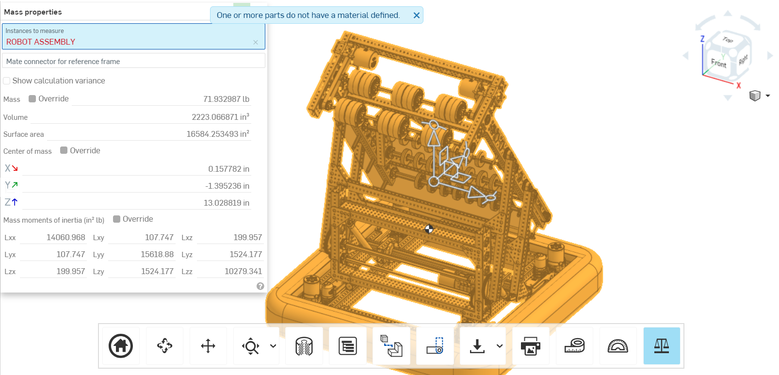
Faithful CAD loaded with mass properties
Most popular CAD tools can calculate the mass properties of solid modeled objects. However, a disciplined approach to CAD work is required for these values to be accurate.
Physical experimentation
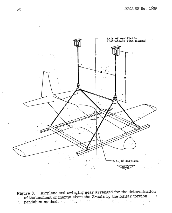
The MoI of irregular objects can be determined experimentally using the bifilar (two wire) vertical axis torsional pendulum method.
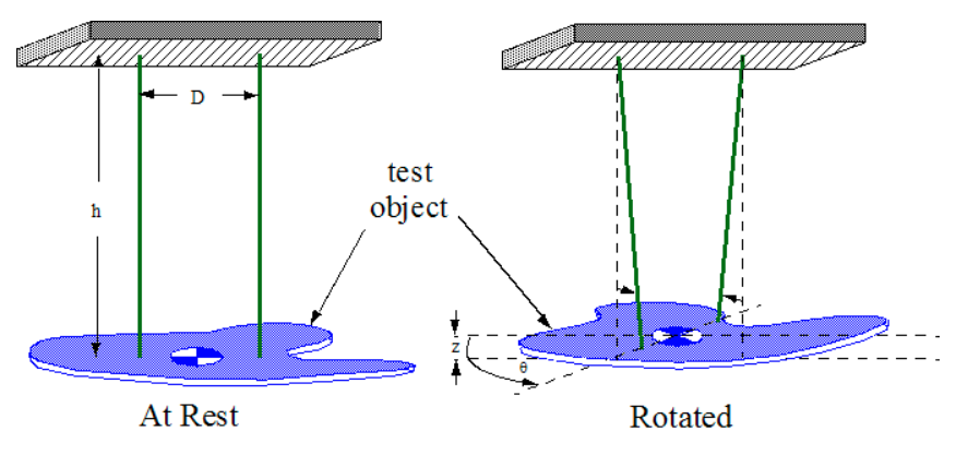
This experiment requires suspending your robot from an overhead support by a pair of parallel strings. Then, after providing an initial push, the frequency of the oscillation is measured by counting the number of swings in a given period.
Warning
Robots are heavy and may fall. Do not suspend robots from an acoustic drop ceiling system, such as you'd find in a classroom. In general, we recommend that you get permission from the building owner before making any attachment to walls, floors, and ceilings, even temporarily.
Tip
If suspending the robot from a ceiling is not feasible, consider constructing a freestanding gantry for this purpose. A typical playground swingset is likely to provide adequate support, and many suitable plans for swingsets can be found on the internet.
A detailed experimental procedure is given in The Experimental Determination of the Moments of Inertia of Airplanes by a Simplified Compound-Pendulum Method, NACA Technical Note No. 1629.